- +1 647 997 6394
- info@hamiltonmetal.ca
Flanges
Our range of Industrial flanges are ideal for application in diverse industry for high pressure and temperature applications. These flanges are designed with precision for easy installation
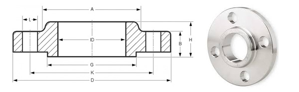
Slip On flanges
Specification :
Size: 1/2″ (15 NB) to 48″ (1200NB)
Standards: ANSI B16.5, ANSI B16.47 Series A & B, MSS SP44, ASA, API-605, AWWA, Custom Drawings
Pressure Ratings: Class 150, PN16
Carbon Steel Slip-on Flanges: ASTM A105/A105N, A350 LF1, LF2 CL1/CL2, LF3 CL1/CL2, A694 F42, F46, F48, F50, F52, F56, F60, F65, F70, A516.60, 65, 70 (Spectacle Blind Flange, Spacer Ring/Spade Flange), Steel RST37.2, C22.8
Stainless Steel Slip-on Flanges: ASTM A182 F202, F304/304L/304H, F316/316L, F316H, F316TI, F310, F321, F904L
Alloy Steel Slip-on Flanges: ASTM A182 F1, F5, F9, F11, F22, F91
Special Alloy Slip-on Flanges: Duplex, Super Duplex, Nickel Alloys
Flange Face Type: Flate Face (FF), Raised Face (RF), Ring Type Joint (RTJ)
Coating/Surface Treatment: Anti-rust Paint, Oil Black Paint, Yellow Transparent, Zinc Plated, Cold and Hot Dip Galvanized
Specification/ Dimension of Slip On flanges :
| Drilling | |||||||||
|---|---|---|---|---|---|---|---|---|---|
| Nominal Bore | Dia.(D) | Thick.(E) | Dia.(F) | Dia.(B) | Dia.(A) | Height1(H) | Nbr | Holes | Dia.(C) |
| 1/2″ | 90 | 9.6 | 35.05 | 30 | 22.2 | 14 | 4 | 15.87 | 60.3 |
| 3/4″ | 100 | 11.2 | 42.93 | 38 | 27.7 | 14 | 4 | 15.87 | 69.9 |
| 1″ | 110 | 12.7 | 50.80 | 49 | 34.5 | 16 | 4 | 15.87 | 79.4 |
| 1 1/4″ | 115 | 14.3 | 63.50 | 59 | 43.2 | 19 | 4 | 15.87 | 88.9 |
| 1 1/2″ | 125 | 15.9 | 73.15 | 65 | 49.5 | 21 | 4 | 15.87 | 98.4 |
| 2″ | 150 | 17.5 | 91.95 | 78 | 61.9 | 24 | 4 | 19.05 | 120.7 |
| 2 1/2″ | 180 | 20.7 | 104.65 | 90 | 74.6 | 27 | 4 | 19.05 | 139.7 |
| 3″ | 190 | 22.3 | 127.00 | 108 | 90.7 | 29 | 4 | 19.05 | 152.4 |
| 3 1/2″ | 215 | 22.3 | 139.70 | 122 | 103.4 | 30 | 8 | 19.05 | 177.8 |
| 4″ | 230 | 22.3 | 157.22 | 135 | 116.1 | 32 | 8 | 19.05 | 190.5 |
| 5″ | 255 | 22.3 | 185.67 | 164 | 143.8 | 35 | 8 | 22.22 | 215.9 |
| 6″ | 280 | 23.9 | 215.90 | 192 | 170.7 | 38 | 8 | 22.22 | 241.3 |
| 8″ | 345 | 27.0 | 269.75 | 246 | 221.5 | 43 | 8 | 22.22 | 298.5 |
| 10″ | 405 | 28.6 | 323.85 | 305 | 276.2 | 48 | 12 | 25.40 | 362.0 |
| 12″ | 485 | 30.2 | 381.00 | 365 | 327.0 | 54 | 12 | 25.40 | 431.8 |
| 14″ | 535 | 33.4 | 412.75 | 400 | 359.2 | 56 | 12 | 28.57 | 476.3 |
| 16″ | 595 | 35.0 | 469.90 | 457 | 410.5 | 62 | 16 | 28.57 | 539.8 |
| 18″ | 635 | 38.1 | 533.40 | 505 | 461.8 | 67 | 16 | 31.75 | 577.9 |
| 20″ | 700 | 41.3 | 584.20 | 559 | 513.1 | 71 | 20 | 31.75 | 635.0 |
| 24″ | 815 | 46.1 | 692.15 | 663 | 616.0 | 81 | 20 | 34.92 | 74 |
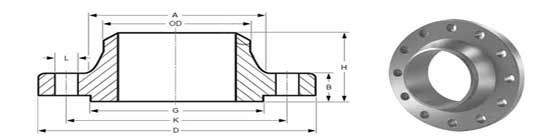
Welded Neck Flanges
Specification :
Size: 1/2″ (15 NB) to 48″ (1200NB)
Standards: ANSI B16.5, ANSI B16.47 Series A & B, MSS SP44, ASA, API-605, AWWA, Custom Drawings
Pressure Ratings: Class 150, PN16
Carbon Steel Weld Neck Flanges: ASTM A105/A105N, A350 LF1, LF2 CL1/CL2, LF3 CL1/CL2, A694 F42, F46, F48, F50, F52, F56, F60, F65, F70, A516.60, 65, 70 (Spectacle Blind Flange, Spacer Ring/Spade Flange), Steel RST37.2, C22.8
Stainless Steel Weld Neck Flanges: ASTM A182 F202, F304/304L/304H, F316/316L, F316H, F316TI, F310, F321, F904L
Alloy Steel Weld Neck Flanges: ASTM A182 F1, F5, F9, F11, F22, F91
Special Alloy Weld Neck Flanges: Duplex, Super Duplex, Nickel Alloys
Flange Face Type: Flate Face (FF), Raised Face (RF), Ring Type Joint (RTJ)
Coating/Surface Treatment: Anti-rust Paint, Oil Black Paint, Yellow Transparent, Zinc Plated, Cold and Hot Dip Galvanized
Specification/ Dimension of Welded Neck Flange :
| ANSI, ASME, ASA, B16.5 150lb/sq.in. WELDING NECK FLANGE RF | |||||||||||
| ø | D | b | g | m | a | J* | h | k | Holes | l | Kg. |
| 1/2" | 88,9 | 11,1 | 34,9 | 30,2 | 21,3 | 15,7 | 47,6 | 60,3 | 4 | 15,9 | 0,500 |
| 3/4" | 98,4 | 12,7 | 42,9 | 38,1 | 26,7 | 20,8 | 52,4 | 69,8 | 4 | 15,9 | 0,700 |
| 1" | 107,9 | 14,3 | 50,8 | 49,2 | 33,5 | 26,7 | 55,6 | 79,4 | 4 | 15,9 | 1,100 |
| 1 1/4" | 117,5 | 15,9 | 63,5 | 58,8 | 42,2 | 35,1 | 57,1 | 88,9 | 4 | 15,9 | 1,500 |
| 1 1/2" | 127,0 | 17,5 | 73,0 | 65,1 | 48,3 | 40,9 | 61,9 | 98,4 | 4 | 15,9 | 1,800 |
| 2" | 152,4 | 19,0 | 92,1 | 77,8 | 60,3 | 52,6 | 63,5 | 120,6 | 4 | 19,0 | 2,700 |
| 2 1/2" | 177,8 | 22,2 | 104,8 | 90,5 | 73,1 | 62,7 | 69,8 | 139,7 | 4 | 19,0 | 4,400 |
| 3" | 190,5 | 23,8 | 127,0 | 107,9 | 88,9 | 78,0 | 69,8 | 152,4 | 4 | 19,0 | 5,200 |
| 3 1/2" | 215,9 | 23,8 | 139,7 | 122,2 | 101,6 | 90,2 | 71,4 | 177,8 | 8 | 19,0 | 6,400 |
| 4" | 228,6 | 23,8 | 157,2 | 134,9 | 114,3 | 102,4 | 76,2 | 190,5 | 8 | 19,0 | 7,500 |
| 5" | 254,0 | 23,8 | 185,7 | 163,5 | 141,2 | 128,3 | 88,9 | 215,9 | 8 | 22,2 | 9,200 |
| 6" | 279,4 | 25,4 | 215,9 | 192,1 | 168,4 | 154,2 | 88,9 | 241,3 | 8 | 22,2 | 11,000 |
| 8" | 342,9 | 28,6 | 269,9 | 246,1 | 219,1 | 202,7 | 101,6 | 298,4 | 8 | 22,2 | 18,300 |
| 10" | 406,4 | 30,2 | 323,8 | 304,8 | 273,0 | 254,5 | 101,6 | 361,9 | 12 | 25,4 | 25,000 |
| 12" | 482,6 | 31,7 | 381,0 | 365,1 | 323,8 | 304,8 | 114,3 | 431,8 | 12 | 25,4 | 39,000 |
| 14" | 533,4 | 34,9 | 412,7 | 400,0 | 355,6 | 336,5 | 127,0 | 476,2 | 12 | 28,6 | 51,000 |
| 16" | 596,9 | 36,5 | 469,9 | 457,2 | 406,4 | 387,3 | 127,0 | 539,7 | 16 | 28,6 | 60,000 |
| 18" | 635,0 | 39,7 | 533,4 | 504,8 | 457,2 | 438,1 | 139,7 | 577,8 | 16 | 31,7 | 71,000 |
| 20" | 698,5 | 42,9 | 584,2 | 558,8 | 508,0 | 488,9 | 144,5 | 635,0 | 20 | 31,7 | 88,000 |
| 22" | 749,3 | 46,0 | 641,2 | 609,6 | 558,8 | 539,7 | 149,2 | 692,1 | 20 | 34,9 | 102,000 |
| 24" | 812,8 | 47,6 | 692,1 | 663,6 | 609,6 | 590,5 | 152,4 | 749,3 | 20 | 34,9 | 119,000 |
| * | The data "J" corresponds to the STD schedule | ||||||||||
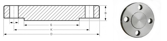
Blind Flanges
Specification :
Size: 1/2″ (15 NB) to 48″ (1200NB)
Standards: ANSI B16.5, ANSI B16.47 Series A & B, MSS SP44, ASA, API-605, AWWA, Custom Drawings
Pressure Ratings: Class 150, PN16
Carbon Steel Blind Flanges: ASTM A105/A105N, A350 LF1, LF2 CL1/CL2, LF3 CL1/CL2, A694 F42, F46, F48, F50, F52, F56, F60, F65, F70, A516.60, 65, 70 (Spectacle Blind Flange, Spacer Ring/Spade Flange), Steel RST37.2, C22.8
Stainless Steel Blind Flanges: ASTM A182 F202, F304/304L/304H, F316/316L, F316H, F316TI, F310, F321, F904L
Alloy Steel Blind Flanges: ASTM A182 F1, F5, F9, F11, F22, F91
Special Alloy Blind Flanges: Duplex, Super Duplex, Nickel Alloys
Flange Face Type: Flate Face (FF), Raised Face (RF), Ring Type Joint (RTJ)
Coating/Surface Treatment: Anti-rust Paint, Oil Black Paint, Yellow Transparent, Zinc Plated, Cold and Hot Dip Galvanized
Blind Flange Dimensions :
| Drilling | ||||||
|---|---|---|---|---|---|---|
| Nominal Bore | Dia.(D) | Thick.(E) | Dia.(F) | Nbr | Holes | Dia.(C) |
| 1/2″ | 90 | 9.6 | 35.05 | 4 | 15.87 | 60.3 |
| 3/4″ | 100 | 11.2 | 42.93 | 4 | 15.87 | 69.9 |
| 1″ | 110 | 12.7 | 50.80 | 4 | 15.87 | 79.4 |
| 1 1/4″ | 115 | 14.3 | 63.50 | 4 | 15.87 | 88.9 |
| 1 1/2″ | 125 | 15.9 | 73.15 | 4 | 15.87 | 98.4 |
| 2″ | 150 | 17.5 | 91.94 | 4 | 19.50 | 120.7 |
| 2 1/2″ | 180 | 20.7 | 104.63 | 4 | 19.50 | 139.7 |
| 3″ | 190 | 22.3 | 127.00 | 4 | 19.50 | 152.4 |
| 3 1/2″ | 215 | 22.3 | 139.70 | 8 | 19.50 | 177.8 |
| 4″ | 230 | 22.3 | 157.23 | 8 | 19.50 | 190.5 |
| 5″ | 255 | 22.3 | 185.67 | 8 | 22.22 | 215.9 |
| 6″ | 280 | 23.9 | 215.90 | 8 | 22.22 | 241.3 |
| 8″ | 345 | 27.0 | 269.75 | 8 | 22.22 | 298.5 |
| 10″ | 405 | 28.6 | 325.85 | 12 | 25.4 | 362.0 |
| 12″ | 485 | 30.2 | 381.00 | 12 | 25.4 | 431.8 |
| 14″ | 535 | 33.4 | 412.75 | 12 | 28.57 | 476.3 |
| 16″ | 595 | 35.0 | 469.90 | 16 | 28.57 | 539.8 |
| 18″ | 635 | 38.1 | 533.40 | 16 | 31.75 | 577.9 |
| 20″ | 700 | 41.3 | 584.20 | 20 | 31.75 | 635.0 |
| 24″ | 815 | 46.1 | 692.15 | 20 | 34.92 | 749.3 |